|
Step 1. Tools > Terrain Geometry Maker > Terrain Geometry Maker
Use the CAD DXF file to set the bounds of the analysis area and save it as a file (*.tms format) that can be used in GTS NX. Activating this function creates a new window called MIDAS/TGM.
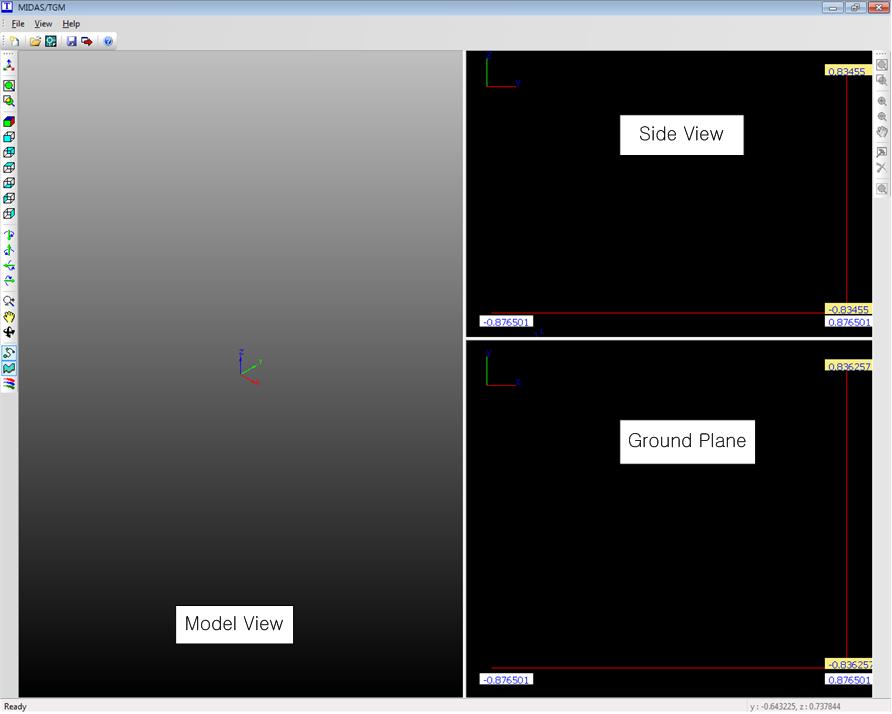
<MIDAS/TGM>
Step 2 : File > Import DXF
Import the AutoCAD DXF file.
<Import AutoCAD DXF file>
[Visible layers]
The layers that are needed for the terrain geometry out of all the layers in the AutoCAD DXF files. The unused layers are selected and moved to the invisible layer.
[Invisible layers]
The layers in the AutoCAD DXF file that are not used for the terrain geometry.

Step 3 : Set analysis boundary
Move the mouse to the area to be modeled and click the Terrain geometry information icon ( ) on the right toolbox to set the analysis boundary. ) on the right toolbox to set the analysis boundary.
Step 4 : Set section zone
<Terrain geometry information>
[Base Contours]
Select the minimum zone that contains the analysis boundary by dragging on the XY plane.
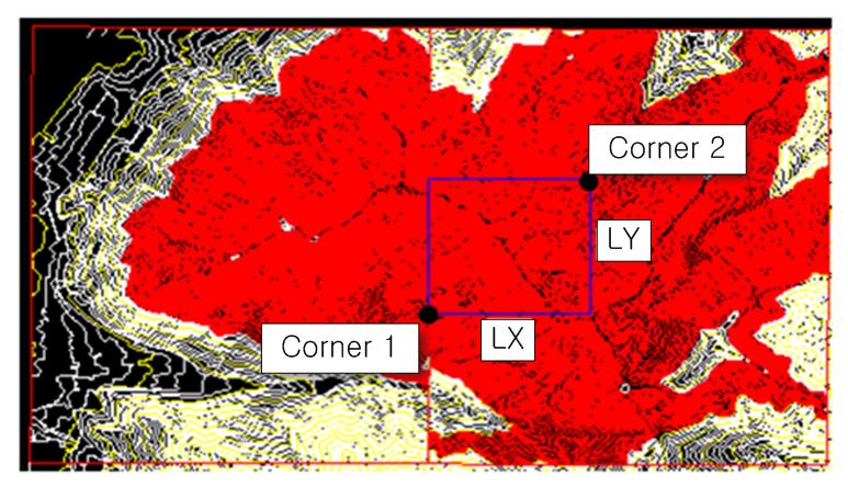
[Geometry Zone (Rectangle)]
Specify the rectangular analysis boundary that is within the base contour zone. Corner 1 and Corner 2 are the diagonal corners that specify the rectangular boundary. Lx, Ly specify the X axis and Y axis lengths of the specified boundary. Click the Display area to view the specified boundary on the plane.
[Number of Sampling Points]
Specify the number of sampling points in the selected region with respect to the X direction and Y direction.
<Example of Terrain geometry information zone>
Step 5 : Check geometry face
Check the geometry face on the View model window.
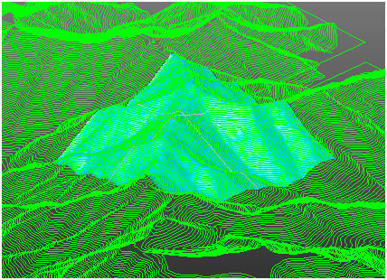
<Example of Terrain geometry information zone>
Step 6 : File > Export surface
Save the generated terrain face as a *.tms file that can be used in the GTS NX.
Step 7 : Main menu : Tools > Terrain Geometry Maker > Import TMS file
Import a generated *.tms file using the MIDAS/TGM function.
|

